Welcome to my blog!

Here I am, enjoying nature in a lost forest
Contact: muguruzainigo@gmail.com
Improving image displaying design
This time, I have come back to the previous work I did with VGA. As I mentioned in the post I wrote, I wanted to upgrade the design to be more useful.
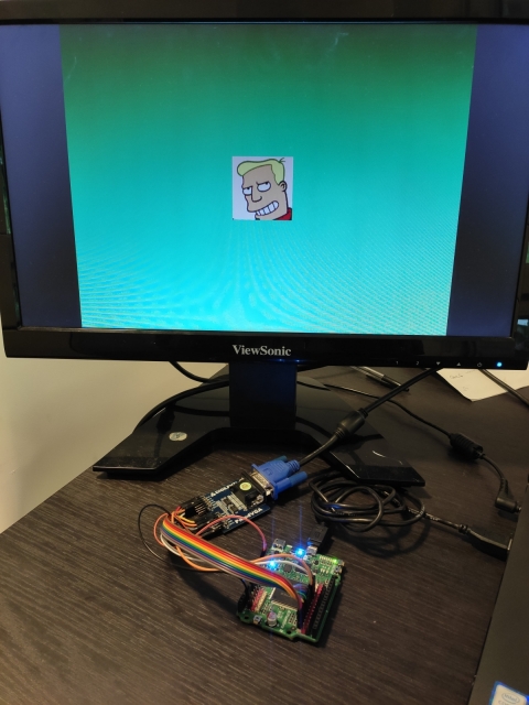
This time, I have added an image receiving functionality to the design. This allows you to send hexadecimal image files to the board using serial communication. Once the the file is sent, the new image is displayed. Let’s see what I have added to the previous design and discuss some technical details.
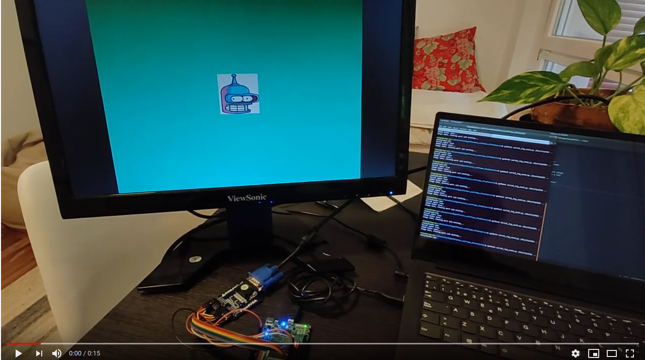
But first, check the next video to see how it works:
You can find the design in a separated repository,
as I decided to use FuseSoC as build system, replacing the Makefiles I was using.
The first block I have added is a serial communication read module. This module reads the
rx line and provides the received 8-bit data at its output, using a data ready
signal pulse to signal it. I have reused the FPGAwars uart-rx
for that purpose.
This module contains a state machine that waits till rx goes low, and stores the
received bits. You can configure the baud rate of the communications, to fit your
needs.
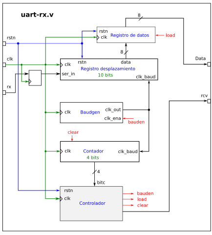
functional blocks of UART RX module, taken frome here
Thanks to this module, the FPGA will be able to read the new image file sent from the computer, but still we need to store the image in RAM and display it. For such a purpose, I have decided to create small state machine that controls if the FPGA reads the serial or displays the image.
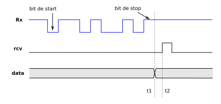
UART RX cronogram taken frome here
As the embedded RAM in the iCE40H4XK allows me to create just an 8-bit 100x100 pixel image, I have decided to keep it. I could add a FIFO, splitting the RAM, to store the new image but this would mean to sacrifice the size (or the color palette) of the image.
I decided to use the read and write capabilities of the RAM. To control it, I used a two-state state machine. This allows to avoid simultaneous read and writes from the RAM.
By default, the state machine is in display mode, reading the stored image in the RAM and displaying it through VGA.
Once the rx generates the start bit, the state machine
changes to write state. In this state, the uart rx provides the data.
This new data is stored in the RAM, using the data ready pulse to detect
when a new chunk has arrived.
As the new image is still not available, meanwhile, the image generator creates a light blue color in the screen.
Once the new image is received, the state machine goes back to display mode, putting the RAM into read mode and displaying the image again.
Practicing crossing domain clock
The default clock of the design is of 25MHz. This is created by the PLL of the board I am using. This is required to meet the VGA timings. But the serial communication does not need such a fast clock.
As I have been reading about crossing domain clock, I decided to put it in practice. Before talking about this topic, I want to explain a bit which are the design’s clock domains. If we divide it into functional blocks, it would look like the next diagram:
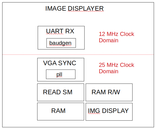
The UART RX module uses the board’s 12MHz clock and the rest of the design works under 25MHz. This implies that some signals in the design work at different speed and this needs to be treated carefully.
The data ready is under 12MHz domain and it is read by the part that is responsible
of writing the new data in RAM, which works at 25MHz. To avoid metastability,
the signal data ready is registered using some flip-flops, like this:
always @(posedge clk_sys) begin
	data_rdy_rx       <= data_rdy;
	data_rdy_ram_prev <= data_rdy_rx;
  data_rdy_ram      <= data_rdy_ram_prev;
  data_rdy_new      <= data_rdy_ram;
As we can see, this always block is executed each time clk_sys positive edge
occurs. This clock is the 25MHz clock. This registers also allows to check a
positive edge of the signal later in the design:
if (data_rdy_new == 1 && data_rdy_ram == 0 ) //Posedge happened, new data
This way, any conflict that could arise is avoided. In addition, as the serial
read line could change asynchronously, I have used the same method to avoid problems.
This signal is also registered in the same always block:
rx_reg_prev_3 <= rx;
rx_reg_prev_2 <= rx_reg_prev_3;
rx_reg_prev   <= rx_reg_prev_2;
rx_reg        <= rx_reg_prev;
And the registers are used to decide when the state machine needs to change to write mode:
if (rx_reg_prev == 0 && rx_reg == 1 && write_addr == 0) //RX Start condition
This is making the design a bit more complicated, but I think it worth the effort.
If you want to understand better crossing clock domain topic, please check the next links:
Sending new images
In order to send new images, I have created a python script that sends through serial a selected image. I have added three of them: Futurama’s Bender, Fry and Zapp Brannigan’s image. This is the result:
To use the script properly, you need to specify the serial port in which the board is attached and the image you want to load:
$ cd image_displayer/sw
$ python3 serial_img_send.py /dev/ttyUSB1 ../data/bender.mem
Using FuseSoC as package manager
This time, I have decided to create a FuseSoC core of the design. This has allowed
me to forget about creating a Makefile to add the test benches simulation and
the synthesis of the module.
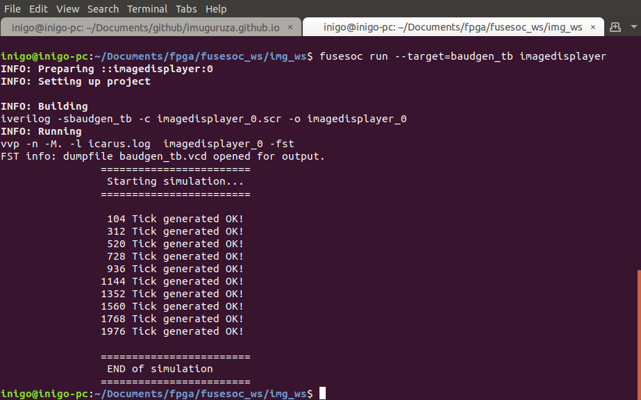 baudgen module test bench execution using FuseSoC
It has been also easier to add parameters, for example, the baud rate of the serial communication or the default board clock value. This parameters are passed from the core file to the Verilog files, easing the parametrization of the design.
It seems straightforward to add different FuseSoC cores to your own (complex) design. As parameters are easy to handle too, now I understand better the potential of using such a package manager/compiling tool in designs.
TODOs
As I have used already the image generator twice, I think it would be a good idea to wrap it around a module and may be offer it as a FuseSoC core, to ease the reuse of it.
In addition to this, the python script could be improved to support more image files, because the creation process is the same as before, and it is not as easy as it should.